


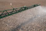


Rotary spaders have been used in Europe for more than a century as a primary tillage tool where burial of large amounts of surface crop residue is required, but have only recently been adopted in Australia for burial of the soil surface layer, incorporation of amendments and soil mixing to address soil constraints.
Uses include dilution of water-repellent surface soil, burying a nutrient-rich topsoil and/or amendments applied to the surface (such as lime, organic materials and clay) and, where accessible, mixing heavy-textured subsoils into a sandy surface soil.
Rotary spaders are able to thoroughly mix soil throughout their working depth and incorporate large volumes of material applied to the soil surface. Although they generally provide superior mixing than tyne and disc equipment, spaders typically have a slower work rate.
If the primary soil constraint is compaction or a hard duplex layer within the working depth of the spader, this should be removed, typically using a deep ripper, before the spading operation. The rotary spader consists of several large blades (referred to as spades) spaced across and around a rotor that engage the soil. The rotor is driven by the tractor power take-off at constant rotational speed.
The blades lead the rotor and cut downward into the soil, taking surface materials with them as the machine passes over the top. The action of the blades draws surface soil down into the soil profile and brings deeper soil to the surface as the blades exit the soil. There are a range of blade shapes, sizes, lengths and spacings.
Most broadacre spaders have an optimal working depth of 300 to 350 millimetres and are recommended to work at four to seven kilometres per hour. Due to the fixed rotational speed, each blade enters the ground at a specific point and time, and the distance between blades is known as the bite length (see Figure 1).
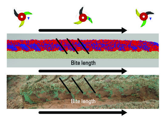
Figure 1 Rotary spader showing direction of movement (top); discrete element method simulation showing impact of the rotary spade and bite length of spade (middle); and a field test with coloured sand showing actual bite length (bottom). Source UniSA
The bite length is a function of the fixed rotor speed and the forward operating speed of the machine. As the forward speed decreases relative to a fixed rotor speed, the bite length decreases, and mixing efficiency improves.
For a better understanding of the effects of the spader set-up and operation on the mixing ability, discrete element method (DEM) simulations were carried out. This involved calibrating a model simulation to a field soil, including the full-scale spader geometry in the model. This geometry was then run with all the working parameters that were used to operate the machine in the field.
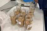
In both the simulations and field trial validations, a blue sand tracer was applied to the soil surface as a visual marker which, when analysed using digital photography, provided an accurate method of quantifying the mixing of the surface soil layer into the profile.
The effect
Model simulations and validation field trials have provided a better understanding of the rotary spader's mixing ability.
First, if a cross-section through the width of spaded soil is excavated, there is generally more surface material along the lines at which the blades are spaced across the rotor than between the blades, and this material tends to be deeper in the profile, especially at the bottom of the blade bite length path (see Figure 2).
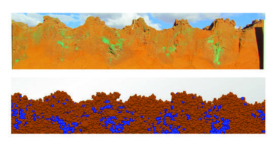
Figure 2 Cross-section of a rotary spaded profile in the field using coloured sand (top) and discrete element method simulation (bottom). Source UniSA
Second, if a section of spaded soil is excavated along the direction of the spader, the bite length of each individual blade can clearly be seen.
Finally, if the soil is removed in layers starting from the surface through to the working depth of the spaded soil profile, an increase in surface material (blue tracer) can be seen along the physical spader blade rows, with a greater proportion of topsoil in the top half of the profile and declining as the working depth is reached. If many of these are looked at, a more representative picture of the depth of burial can be seen, as in Figure 4.
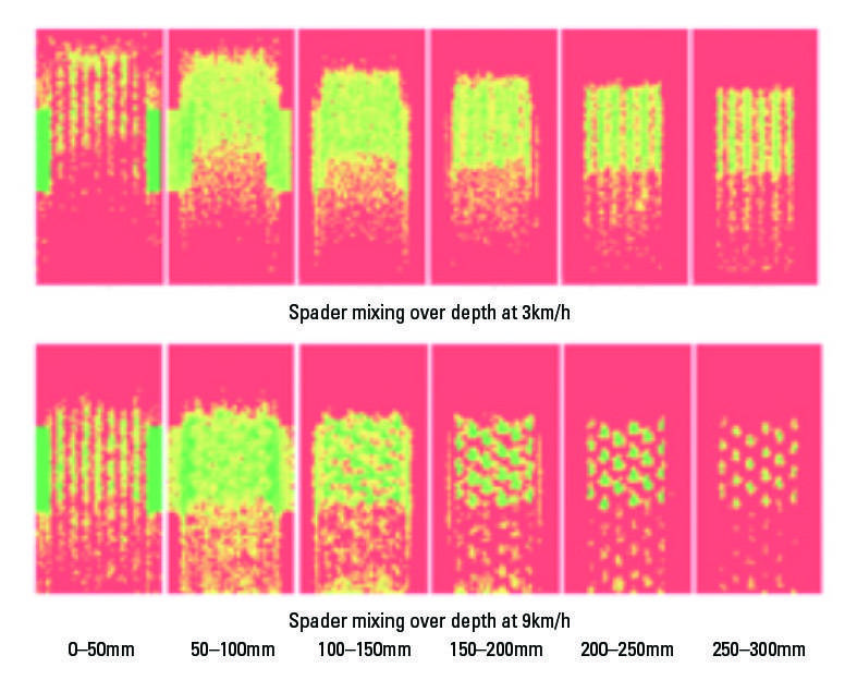
Figure 3 Discrete element method simulation of the effect of spading at 3 and 9km/h on bite length and surface material burial down the soil profile at 50mm increments. Source UniSA
Figure 3 illustrates six soil layers from the surface to the working depth of the spader. This shows that a spader its most effective at burying the surface layer in the top two-thirds of its working depth, and the incorporation of the topsoil decreases as the working depth is increased.
Incorporation of the topsoil is also decreased by increasing the forward speed of the spader from 3 to 9km/h.
As mixing is affected by bite length and bite length is dependent on forward speed, these should be carefully considered for the amount, depth and quality of mixing required.
Model simulations shown in Figure 4 illustrate how the mixing uniformity decreases as forward speed of spading is increased, and the likelihood of high concentrations of surface material ending up in pockets ('hotspots') increases, especially at depth. This should be considered in relation to the soil constraints being addressed and amelioration method.
If an amendment has a low mobility within the soil, such as lime, uniform mixing of the product may give more immediate and better crop responses.
On the other hand, if a product has a high nutrient concentration, such as a manure, and this is mixed throughout the soil, nutrients may become rapidly available causing toxicity or excessive early crop vigour.
In this case it might be more beneficial if the product is left in pockets in the soil, so a greater forward speed and longer bite length of the spader might be more preferable. This is the focus of further GRDC-invested postdoctoral research being undertaken at the University of South Australia.
The main implications of spader set-up for growers are around machine work rates and operating costs.
For example, if a product needs to be well-mixed deep into the profile, then a slow ground speed should be used - as shown in Figure 4 - which will slow the work rate and add expense.
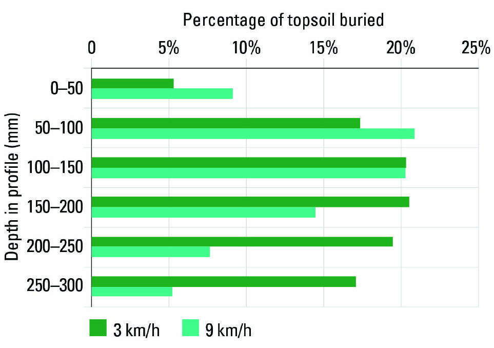
Figure 4 - DEM simulation of the effect of spading speed on the percentage of surface soil buried through the working profile. Source UniSA
If a product does not need to be mixed well, then a fast operation can be carried out, or even an alternative tillage method to achieve a light mixing at lower cost can be considered, such as one-way discs.
Spaders are designed to cultivate the whole soil profile to the working depth, so post-spading crop establishment and soil erosion risks need to be considered.
As the spader loosens soil and buries all surface residues, the surface is left loose, soft and prone to wind erosion.
Machine components and attachments such as large-diameter rubber tyres should be considered to consolidate the loose surface soil and provide stability for seeding operations.
The attachment of direct seeding as part of the spading operation may be used to reduce the critical exposure time and detrimental impacts of rotary spading on the seedbed establishment. This spade and sow approach is currently being evaluated in the field.
Strip spading, leaving standing stubble between the strips, may be another option to reduce erosion risk.
More information: Dr Stephen Davies, DPIRD, 08 9956 8515, stephen.davies@dpird.wa.gov.au; Dr Chris Saunders, UniSA, 08 8302 3664, chris.saunders@unisa.edu.au; Dr Lynne MacDonald, CSIRO, 08 8273 8111, Lynne.Macdonald@csiro.au